Pint 4 - pencil tool
This article is going to cover implementation of a tool a bit more complicated than the rect tool we’ve already talked about. The pencil tool may intuitively sound like the simplest one out there, but we’ll see how it’s not exactly true.
The reader will also be able to notice how serious I am about this and how accurate this implementation is gonna be1. My goal is pixel-perfect match with the original Paint. There are surely a ton of algorithms that would yield visually acceptable results, but I really want to be exact. We’re going to explore some possible approaches, most of which were dead-ends.
Studying the original
Before programming any tool, we first have to carefully study it and understand how it works. Paint’s pencil tool is seemingly simple, but starts to show some intricacies once you try to reimplement it faithfully.
When the user drags their mouse across the screen, the canvas is filled with the selected color along the cursor’s path. One might naively think it just colors the pixel at mouse position every frame and calls it a day. However, mouse movement can be (and usually will be) faster than the refresh rate, introducing holes in the path. So, the line’s integrity would depend on the user’s movement speed. Not ideal, to say the least.

That means Paint must be keeping track of the previous frame’s mouse position and connecting the current mouse position to it. In other words, it has to perform a line rasterization algorithm at its core. I wanted to see how exactly it’s performed. Drawing the lines by hand would be unreliable, because I wouldn’t be sure which pixels were drawn “trivially” at cursor position and which were filled in between.
So I generated an AutoHotkey script to simulate a series of clicks that draw various lines. This way I could be certain there are no intermediate mouse positions and Paint has to rasterize the entire line by itself.
After inspecting, I believe they all exactly match Bresenham’s line algorithm. It’s a solid, widely used method with a long track record.

Next things to study: any extra parameters and modifiers that could be applied to the pencil tool. The obvious one, color, is there. Paint has two active colors, left click draws with primary color, right click draws with secondary color. Also, spacebar works as a left click. Interestingly, clicking the other button while dragging with the first one cancels the drag and discards the results. This is very easy to implement thanks to our scratch+canvas tiles architecture. When a discard happens, we simply throw away the scratch tiles and don’t commit them to canvas. Note these rules are actually obeyed by most of the tools.
Pencil tool isn’t influenced by fill and outline parameters, they are disabled. It does, however, have a thickness.
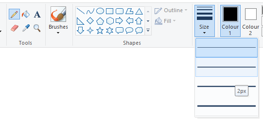
Paint draws an approximation of a circle with a diameter equal to the selected tool thickness. Image below depicts a few of the circles. The blue pixel represents the pixel that was actually clicked. It’s rather obvious for odd diameters, but for even diameters we can see a preference towards the bottom-right quadrant of the circle.

Clicking a single pixel is one thing, but what happens when we drag such a thick pencil? When the pencil is dragged over multiple pixels, the circle pattern is simply duplicated for all of the intermediate positions2. I haven’t noticed any fancy smoothing, antialiasing or changes at the edges of a drag.

Other features include moving the cursor with arrow keys and axis-aligned drawing while holding shift. These behaviors are also honored by some other tools.
Line Rasterization
I decided to first tackle the intermediate pixels rasterization problem. I spent some time thinking how to do this efficiently on GPU. We already know we have to rasterize according to Bresenham’s line algorithm. It’s actually a part of Vulkan spec and we can get the GPU to render lines according to it with draw calls.
This is tempting, but would actually be wildly inefficient. We have to remember the canvas/scratch images are allocated in tiles. A lot of them. Only one tile could be bound as a render target at a time, meaning we’d need a separate dynamic render pass and draw call for each of them. Switching render targets a couple thousand times a frame would be devastating for performance.
Therefore, it must be a fully compute approach. We have to run some computations for every pixel and decide whether the pixel is a part of the line or not. It turns out, that’s more complicated than it sounds.
I first looked into how GPUs solve this in their rasterization engines. For thin lines (1px wide) they generally use the diamond rule3. For each pixel the GPU checks if a line intersects4 a diamond shape inscribed within the pixel. If a pixel’s diamond is hit, the pixel is in the line and it gets colored.
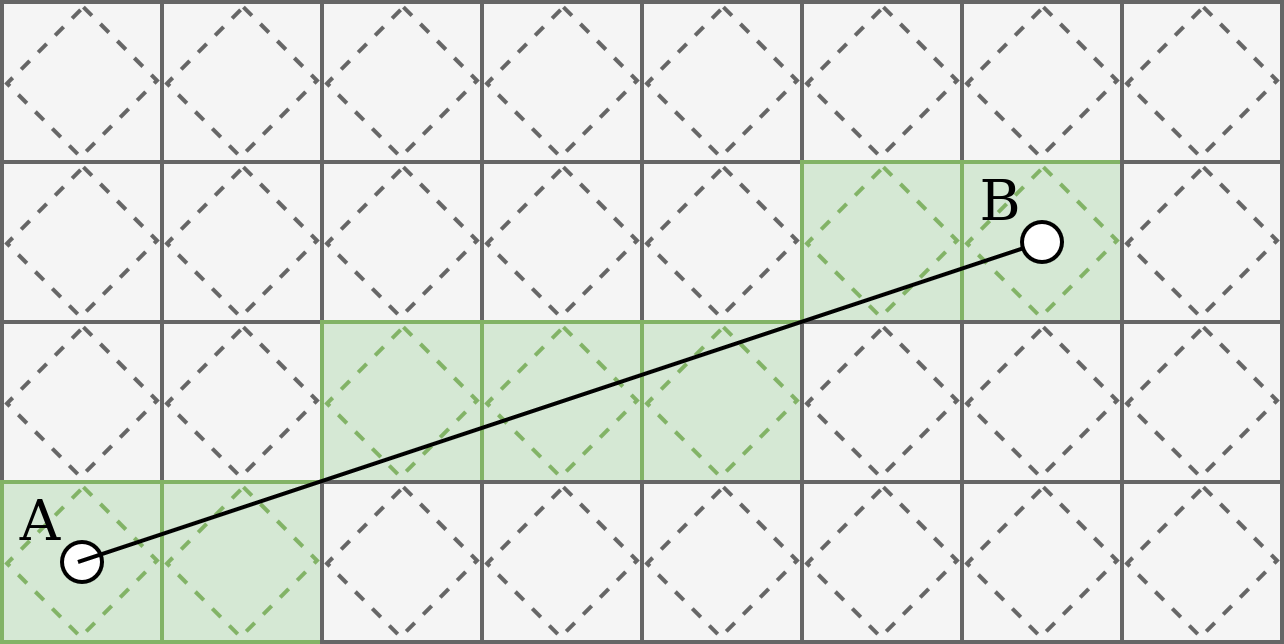
Thick lines (width greater than 1) are usually emulated with quads, either in hardware or in the driver, and rasterized as 2 triangles. I initially implemented the diamond rule in a compute shader, which worked okay. Quad emulation was more tricky, though. I could not get the results to be pixel-perfect. Some pixels were always off when compared with original Paint. I eventually abandoned this approach. Rasterizing a quad extruded from a line is simply a different definition of which pixels belong to a thick line than the one Paint uses and no amount of tweaking could make them match.
I also read a bit about SDFs and how I could just calculate the distance from any pixel P to the segment AB. Gotta admit, I didn’t even try it, being sure it’s not the correct approach. The problem is that an SDF would measure distance to an ideal, mathematical segment, whereas Paint uses a discretized “staircase” line. In other words, it’s a discrepancy between continuous and discrete worlds. You generally need separate classes of algorithms to operate within them.
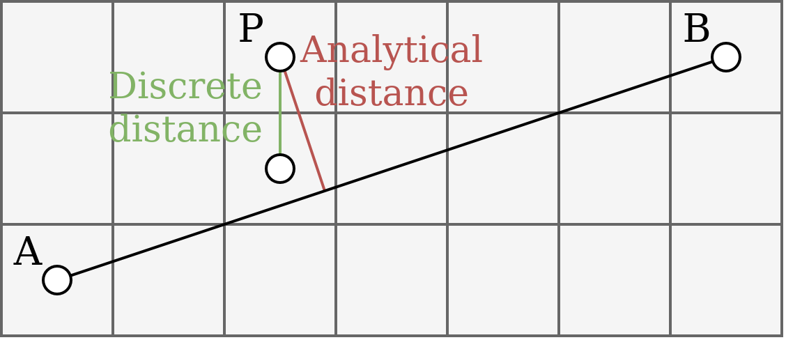
All these approaches were promising at first, but they never worked perfectly. The real Paint seems to be performing an integer-based line rasterization and drawing circles at each rasterized pixel. So, I decided to do the same.
The solution is to first perform Bresenham line rasterization algorithm on CPU5. It gives us a list of pixels that form the line. From now on, we will call them stamps. Rendering the lines onto scratch tiles is now much easier. We generate a buffer with the stamp positions and dispatch a compute shader. Each thread will process an 8x8 block of scratch pixels, checking for each pixel whether it’s within a certain distance from any stamp.
Right, any stamp. We’re doing a loop over the stamps. This may not sound ideal: the faster the stroke, the more stamps we’ll have and the more work the shader will perform. It did not, however, prove to be a performance bottleneck yet, so I’m fine with it for now. More on performance in a later section.
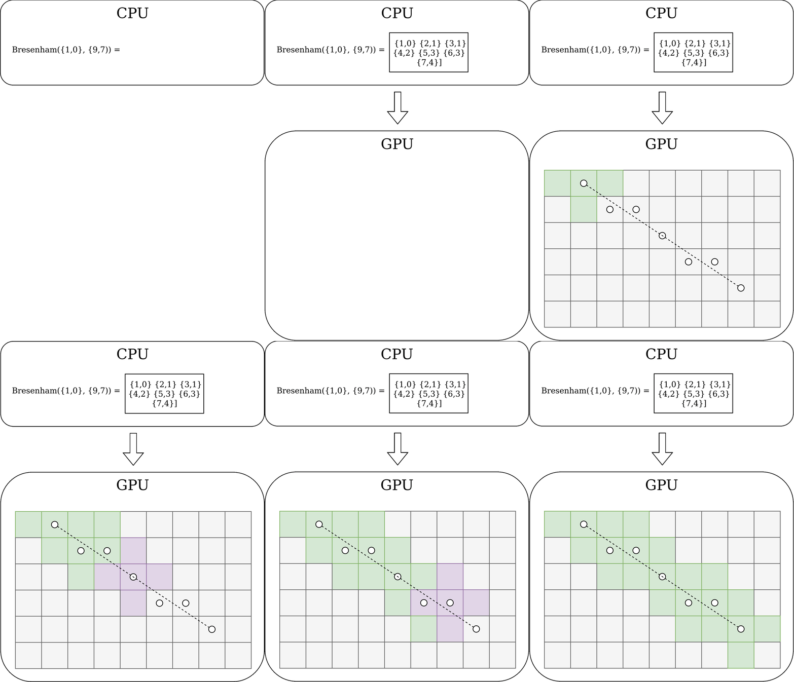
Stamp rendering
Okay, we have our list of stamps, we pass it to the shader, the shader iterates over all stamps for every pixel. How do we check whether a given pixel is within stamp? Well, for pencil thickness equal to $1$ it’s simple. It has to be the same pixel as the stamp. Done.
It again gets difficult for thick lines. Remember the series of samples from original Paint’s pencil for various thicknesses? They are approximations of circles. So let’s use the circle formula. For each pixel $(x,y)$ calculate the distance to the stamp $(s_x, s_y)$ and check whether it’s less or equal to the circle radius $r$.
$$ (x - s_x)^2 + (y - s_y)^2 \le r^2 $$The radius $r$ is the pencil thickness divided by $2$. For odd thickness we also have to offset the stamp position $(s_x, s_y)$ by half a pixel. For even thickness the stamp position is already correct.
The result is almost there. Most circles look good, but notice how it’s wrong for $3px$ case on the image below. Green circles are from original Paint, red circles are from Pint.
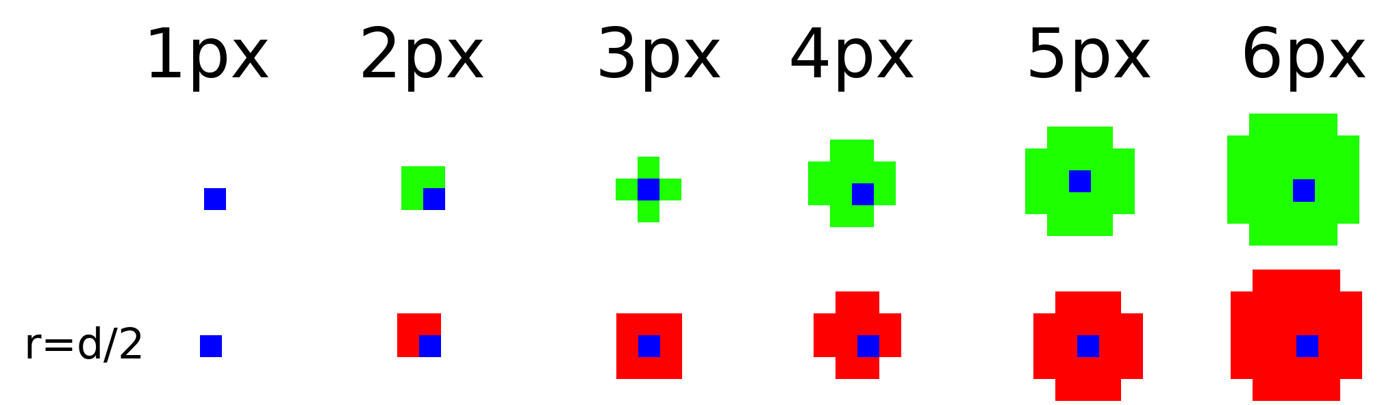
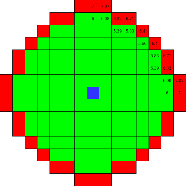
We are coloring too many pixels for $3px$ case. The ones in the corners shouldn’t be colored. We calculate our radius to be the half thickness: $r = \frac32 = 1.5$. So, any pixel with a distance less than $1.5$ will be accepted as part of the circle. Let’s visualize it. The image below illustrates what should be drawn. Green pixels should be in the circle, red ones should be outside. The numbers are distances from the stamp position for each pixel.
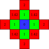
Aha! The corner pixels have distance of $1.42$ which is less than $1.5$. That’s why they are accepted. Maybe the correct way is to divide and truncate: $r = \lfloor \frac32 \rfloor = 1.0$. Let’s see. That fixes the $3px$ case but breaks it for $5px$.
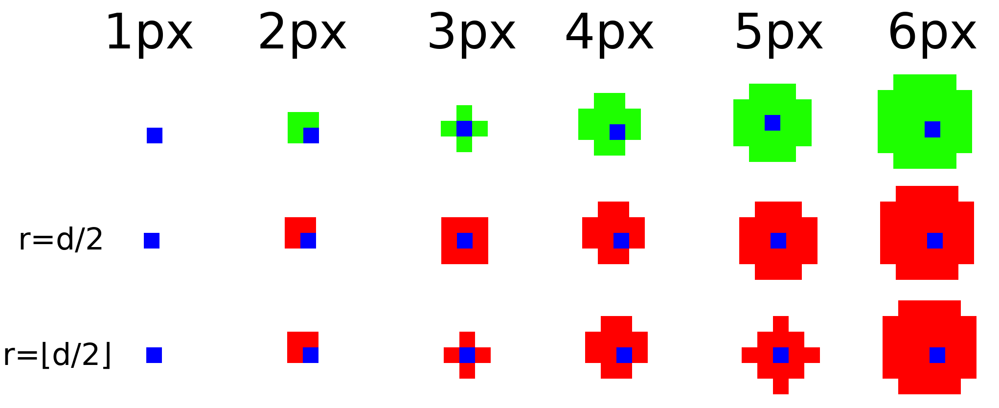
Now we’re rendering too few pixels. Drawing a similar diagram shows that now we should not be truncating after the division in this case. The pixels with a distance of $2.24$ should be accepted.
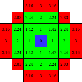
More experimentation shows it’s not even a matter of truncating versus not truncating. Look at the case of $13px$ thickness. We have to accept a pixel with $6.08$ distance, but reject a pixel with $6.32$ distance. The right radius to be used lies somewhere between these two values. It’s neither $6.0$, nor $6.5$.
So, why does Paint do this? What sick mind would devise a radius formula so obscure that we cannot reverse engineer it? The truth is, they probably used a completely different approach and they didn’t calculate the radius like we’re trying to do. It’s likely a scanline algorithm that fills the circle line by line based on some integer maths. I spent some quality time with my go-to LLM, but we couldn’t solve this. The algorithm was always wrong for some circles. And I really didn’t want to introduce specialized branches for problematic thicknesses.
I eventually decided to bruteforce it. I drew every possible circle size in original Paint. The maximum pencil size is 50, so it’s entirely feasible. I marked the center of each circle with a single blue pixel, same as on diagrams above.
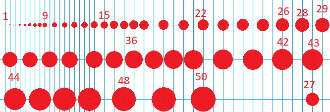
After I’ve made this horrid creation I came back to my favorite LLM and told it to generate a script that would:
- Find every blue pixel. Those are circle centers (stamps).
- For every blue pixel run a flood fill algorithm searching for adjacent red pixels. Calculate the set of pixel coordinates inside the circle and the circle diameter.
- Calculate a bounding box for every circle and generate a set of pixel coordinates that are outside circle.
- Calculate maximum distance of all pixels inside the circle and minimum distance among pixels outside the circle. Set the radius for that circle to be a simple average of those two values.
- Sort the circles by diameter (yeah I messed up the image and they’re not in order).
- Print results as a C++ table.
That worked like a charm. I now have a horrifying lookup table for all the radii with a 6-line comment preceding it. The values don’t seem to be converging to any specific fractional part. They’re just an artifact of a completely different algorithm used by the original Paint, but we’ve managed to fake it pretty faithfully.
constexpr float pencilRadiusLookupTable[] = {
    0.500f,  1.144f,  1.207f,  1.851f,  2.532f,  3.226f,  3.384f,  4.055f,  4.357f,  5.049f,  5.242f,  5.871f,  6.204f,
    7.035f,  7.246f,  8.091f,  8.366f,  9.026f,  9.327f,  10.024f, 10.247f, 11.023f, 11.247f, 11.937f, 12.288f, 13.095f,
    13.247f, 14.018f, 14.265f, 15.050f, 15.248f, 16.047f, 16.217f, 17.044f, 17.234f, 17.986f, 18.303f, 18.934f, 19.274f,
    19.987f, 20.322f, 21.107f, 21.237f, 22.034f, 22.282f, 22.989f, 23.227f, 23.969f, 24.269f, 25.050f,
};
const float radius = pencilRadiusLookupTable[width - 1];
As a sanity check, we can verify this table with some examples we’ve looked at. For example, an entry for 13px circle is $6.204f$ which is correctly between $6.08$ and $6.32$, as we calculated manually.
Performance
After I was finally done with achieving functional correctness, it was time to check how well it performs. Testing on tiny 200x200 image did not show any problems. However, as soon as I tried it out on a large image, I started to notice how sluggish it was.
I wrote a simple benchmark test that creates a 4096x4096 image and draws 10 different lines covering most of the screen.
The benchmark measured performance on both CPU and GPU and printed it to stdout.
This allowed me to easily measure impact of my optimizations without messing with a GUI.
It also let my coding agent verify its own work, so it didn’t have to ask me if a change actually helped.
Initial results were not pretty: CPU=81.2 ms, GPU=147.8 ms.
Optimization 1: segment-aware scratch tiles
I spotted the first, biggest room for improvement when I looked at scratch tiles preview. It’s a debug feature I implemented, but didn’t cover previously. It visualizes which scratch tiles are currently in use. With the pencil tool it looks like this.
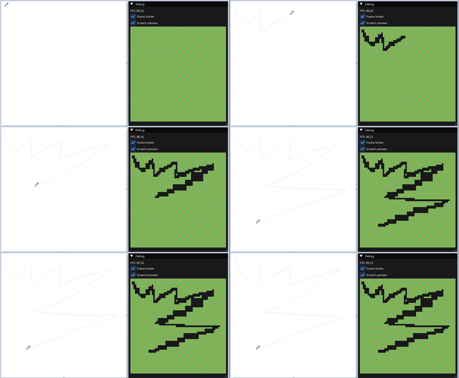
Notice how the thickness of line visible in the preview varies. It’s dependent on the mouse movement speed and direction. It means we’re allocating too many scratch tiles. That takes time and resources to allocate and also requires more processing for the pencil shader (we’re launching a workgroup per tile). It happens because we use a bounding rectangle for start/end points of a line to draw and create scratch tiles for that entire rectangle.
Implementing a tile allocation algorithm specifically for a line segment (while honoring its thickness) brought huge performance improvements: CPU=2.8 ms, GPU=22.3 ms.
CPU timings are now 29x smaller, although admittedly the benchmark exercises a rather extreme, pathological case, so the real-life results may not be that great.
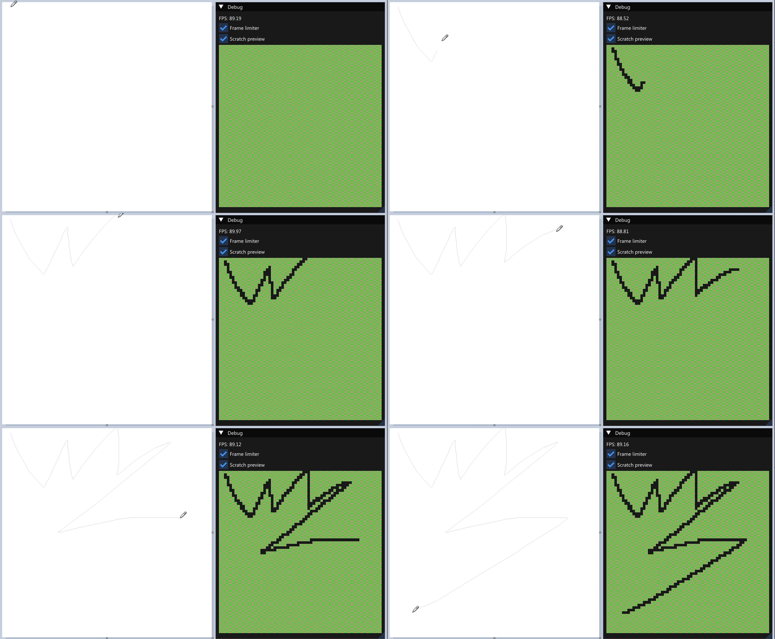
The animation below shows the scratch preview with this change applied. We now get a much thinner line, meaning no useless scratch tiles are allocated.
Optimization 2: device memory pooling
Next I optimized image memory allocation.
Vulkan exposes a very explicit way to allocate images.
You first create an image object, then query how much memory it needs, allocate the memory and then bind it to the image.
Up to this point I had this implemented in a very naive way and I was allocating one VkDeviceMemory object per VkImage object.
Memory allocation is quite costly, and paying that cost once per image meant it piled up fast.
The solution was to create bigger VkDeviceMemory allocations and reuse them for multiple VkImage objects.
This did not improve pencil tool significantly, presumably because it doesn’t require that many tiles.
Current results: CPU=3.0 ms, GPU=20.1 ms.
It did, however, considerably improve the speed of resizing a canvas to a large size, which spawns thousands of images at once. That’s an important enhancement, since the old latency had kept me from manually testing such big canvases.
Optimization 3: barriers
I also looked at pipeline barrier performance, as vkCmdPipelineBarrier was the biggest offender in perf logs.
But first, I have to explain one important implementation detail.
During my initial implementation I decided to put the stamp positions in an array within push constants (faster, but smaller) instead of a separate allocated buffer (slower, but bigger).
As a result, the number of stamps for a dispatch were constrained to a value of 16.
For lines larger than 16 stamps we’re performing multiple vkCmdDispatch calls, each with the same pipeline and resources, but different push constants.
Between every pair of dispatch calls we insert write-to-write image barriers to avoid data hazards in case some tiles are accessed by multiple dispatches.
That can happen for thick lines.
We insert such barrier for every scratch tile image, which is ruthlessly exposed by the benchmark drawing over a screen’s diagonal.
Image barriers are used for two things: layout transitions (e.g. GENERAL->COLOR_ATTACHMENT) and access mask, i.e. cache flushes.
We don’t change the tiles’ layouts in between passes, but we only specify a SHADER_WRITE->SHADER_WRITE cache flush.
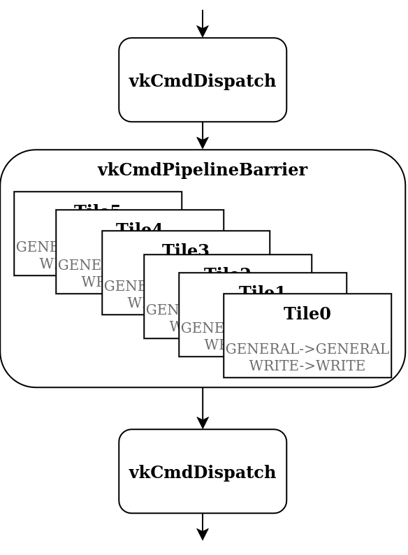
That’s a lot of work for the graphics driver for little benefit.
Desktop GPUs usually do not feature fine-grained cache flushing, so our per-image write-to-write barriers are probably converted to a global shader cache flush anyway.
We can convert the never-ending series of image barriers into a single global memory barrier, that will do the same thing.
This significantly optimizes the processing time: CPU=0.4 ms, GPU=19.1 ms.
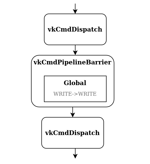
GPU time was still a bit high, though.
The barriers are effectively serializing our dispatches, which is not ideal.
I realized that it may not be needed at all.
See, even if a single tile is accessed within multiple dispatches, the values written to it will be exactly the same.
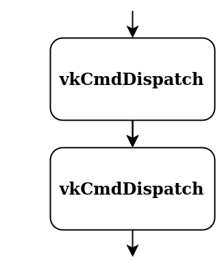
So the data hazards do not matter and we do not need any barriers6!
Removing them altogether finally let us achieve performance acceptable for a (kind of) real-time application: CPU=0.2 ms, GPU=5.9 ms.
Optimization 4: single dispatch
I also tried getting rid of multiple dispatches and just handle all the stamps in a single shader invocation.
The stamp list had to be uploaded into a buffer and the buffer bound to the shader.
This further improved CPU time (less API calls), but dramatically worsened GPU times: CPU=0.02 ms, GPU=24.1 ms.
That’s probably due to more indirection in the shader and the added latency of uploading the data to slower memory.
Optimizations summarized
The table below shows all optimizations discussed previously with their respective performance results.
I settled with the stage 3.2 as the best compromise between CPU and GPU performance.
| Stage | Name | CPU time | GPU time |
|---|---|---|---|
| 0 | Initial | 81.2 ms | 147.8 ms |
| 1 | Segment-aware scratch tiles | 2.8 ms | 22.3 ms |
| 2 | Device memory pooling | 3.0 ms | 20.1 ms |
| 3.1 | Global memory barrier | 0.4 ms | 19.1 ms |
| 3.2 | No barrier between dispatches | 0.2 ms | 5.9 ms |
| 4 | Single dispatch | 0.02 ms | 24.1 ms |
Conclusion
All of this was way more involved than I initially anticipated. Regardless, I’m gonna call it a success. Pint has a pencil tool that 100% matches what the original does, while keeping the performance within real-time application constraints, even for very large images. That sets a precedent for extreme diligence of this reimplementation, and I’ll do my best to hold myself to it.
In the next post we’re going to implement the GUI to finally make this Paint reimplementation really look like Paint.
Of course at the expense of development time and/or my sanity. ↩︎
If you want to impress girls at parties, you can say it’s a Minkowski sum of a circle and the path that was dragged by the mouse. Trust me, it works. ↩︎
The diamond rule is actually a part of most API’s specifications, e.g. D3D11 or Vulkan. It’s also worth noting that Bresenham’s algorithm satisfies the diamond rule. ↩︎
The actual definition is exits not intersects. The algorithm checks if a ray shot from start to end exits the diamond, not just intersects. It leaves out pixels that only have a diamond corner clipped, plus the end pixels, to avoid double-counting where lines connect. It also defines edge rules for similar purpose. I didn’t care for any of these nuances both in my implementation and also in this article. Consistency is key! ↩︎
The main issue with Bresenham algorithm is that it’s not easily parallelizable or rather it’s usually not worth it. In its common form, you have to iterate from start point to end point and gradually build the point list. ↩︎
Do not cite me on that. I’m not entirely sure if I’m correct here, but I cannot think of a situation that would prove me wrong. Suggestions are welcome. ↩︎